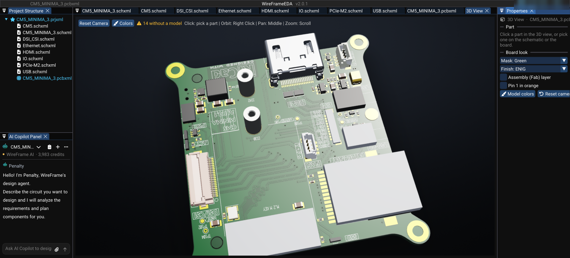
Sample board CM5 Minima — a 6-layer Raspberry Pi CM5 carrier, in 2D and 3D in WireFrame EDA

The CM5 Minima carrier for the Raspberry Pi Compute Module 5, from KiCad's demo projects, imported into WireFrame EDA — four inner planes, an M.2 slot, and the parts drawn from their 3D models.

Sample board CM5 Minima — a 6-layer Raspberry Pi CM5 carrier, in 2D and 3D in WireFrame EDA

CM5 Minima is a compact carrier for the Raspberry Pi Compute Module 5, shipped with KiCad's demo projects. On 61 × 64 mm it carries the module on its two board-to-board connectors (the GPIO side and the high-speed side), an M.2 M-key slot for 2230/2242 cards on PCIe, two USB-C connectors, a 22-pin FPC connector and a LIS3DH accelerometer — on six copper layers.

It is a good example of how a small board ends up with six layers: the module's fast interfaces want a ground plane next to every signal layer, and there is no room to spread out.

Opening it#

The project (CM5_MINIMA_3.kicad_pro) was saved by a KiCad 9 development build. File › Import › KiCad Project (.kicad_pro, .pro)… brings it into WireFrame; the KiCad files stay untouched.
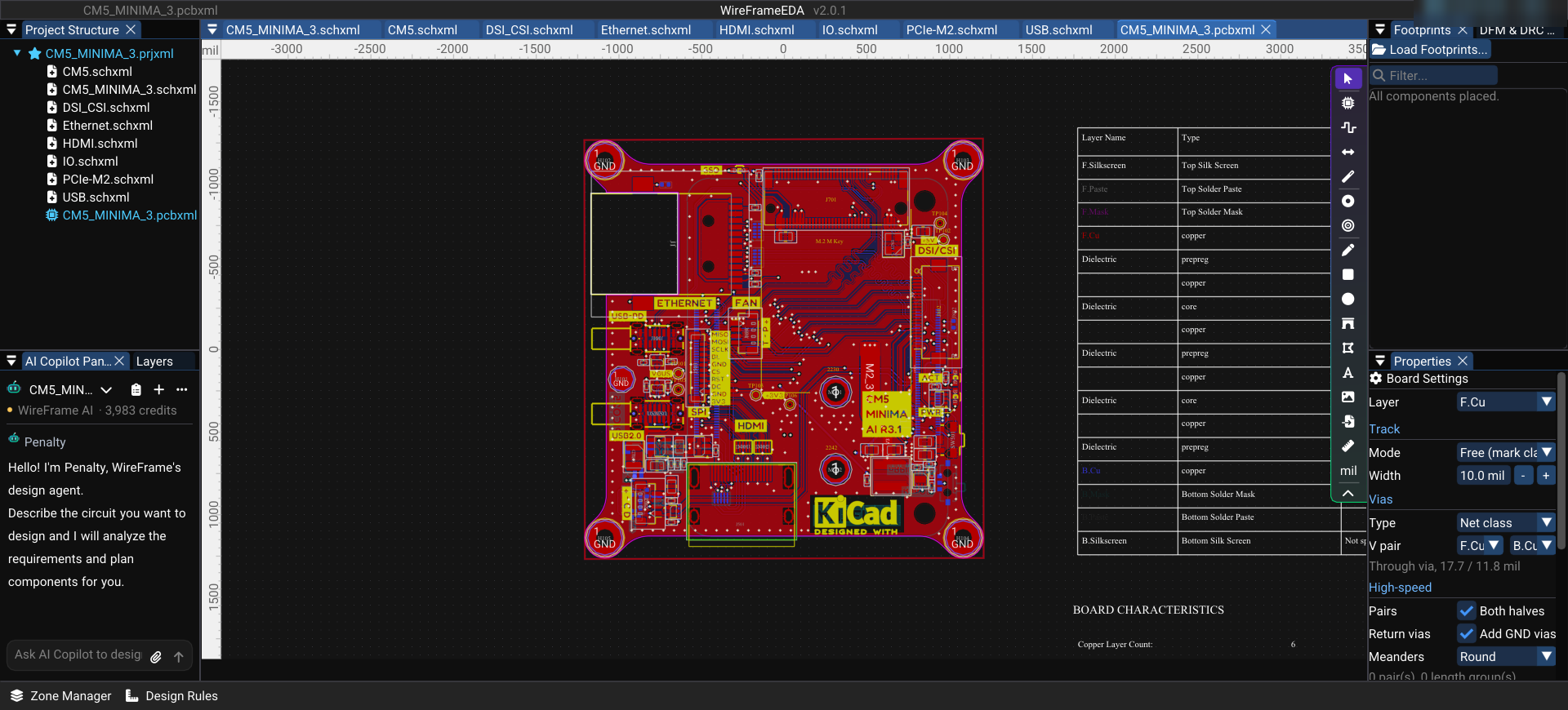
CM5 Minima in WireFrame EDA, all six copper layers shown

For members

Keep reading — it’s free

Sign in or create a WireFrame account to read the rest of this post and every guide on the blog.

  • The rest of this post — about 2 min of reading
  • The same account signs in the WireFrame desktop app
  • Free design tools, no time limit

Sign in to WireFrame

One account for the desktop app and this site.
or with email
Forgot password?

Related posts

KiCad to WireFrame EDA and back: 72/72 round trips identical

Open a KiCad project in WireFrame EDA, work on it and export it back to KiCad: what comes across, what to check, and how the round trip was measured.

Where does your 3.3 V go? DC IR drop on a real board

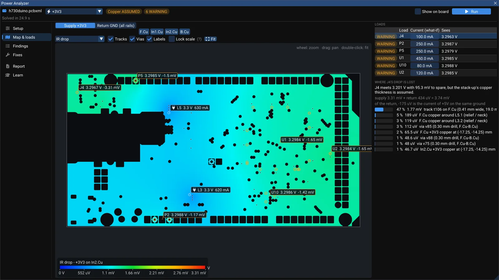
WireFrame's Power Analyzer solves a rail's real copper — supply and return — and splits each load's voltage drop exactly over the tracks, necks and vias that cause it. A walk through the +3V3 rail of the open-source h730duino.

A USB pair at 107.8 Ω — high-speed checks that show their evidence

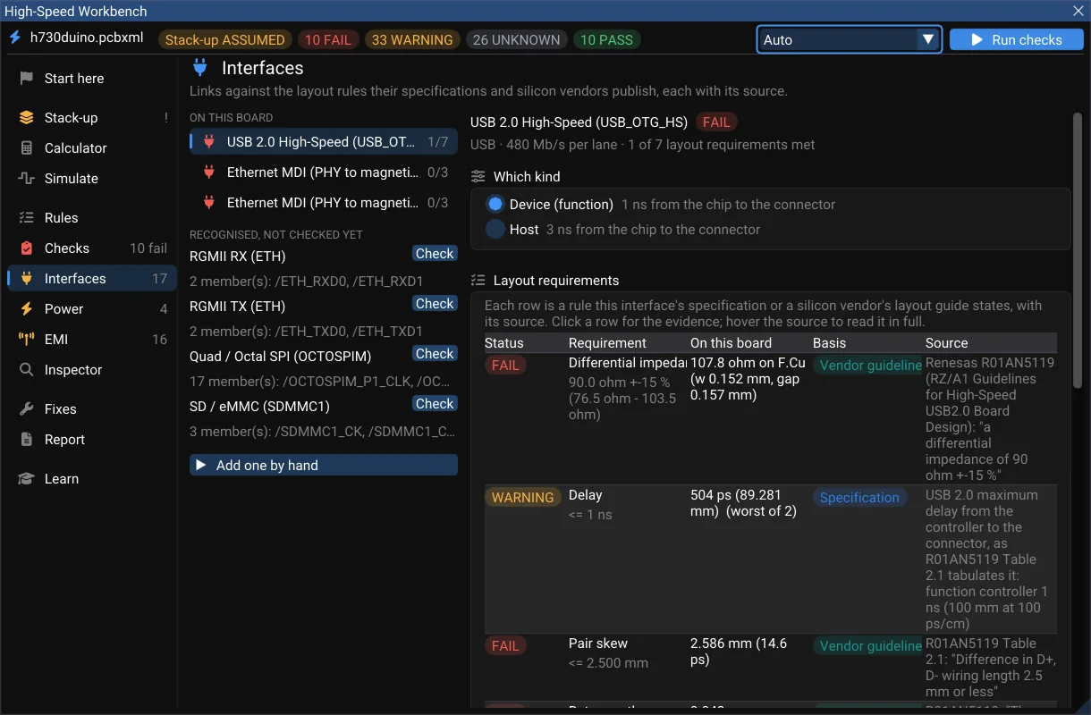
Running WireFrame's High-Speed Workbench on the open-source h730duino board — the USB 2.0 pair's impedance, skew and common mode, its EMI margin, and the fix — with the method and the source behind every number.