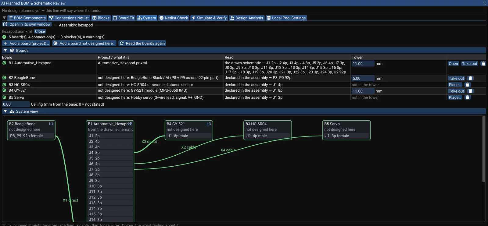
reinforcement-autonomous-hexapod is an open-source six-legged robot on GitHub by NguyenTrongPhuc552003: 18 servos (3 per leg) driven from Linux on a BeagleBone AI, with its own kernel drivers, a kinematics library, several gaits and even reinforcement learning (TD3). According to the repository it is an open-source project and is actively evolving.
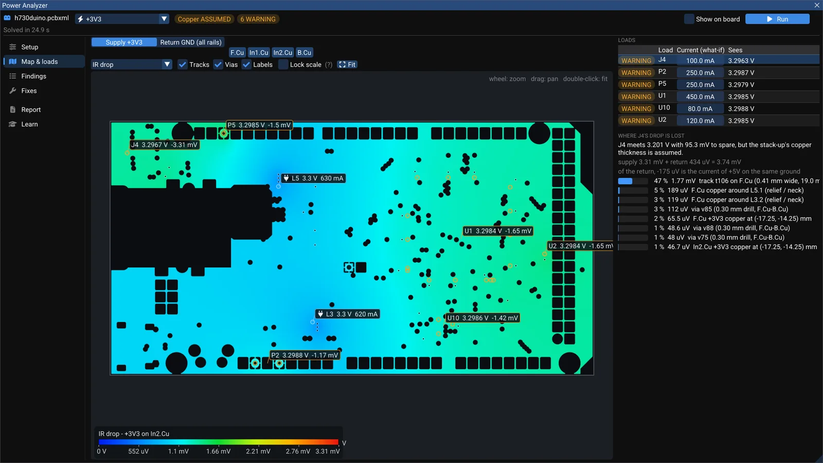
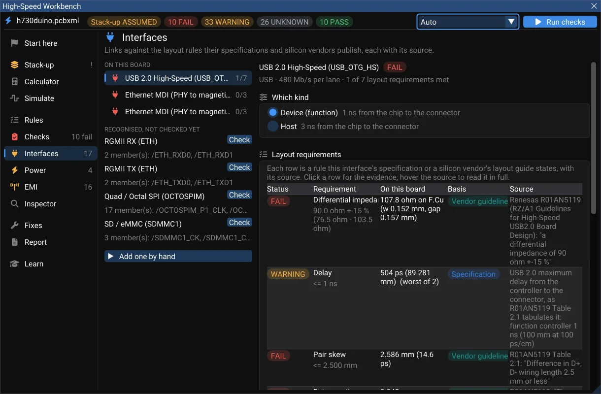
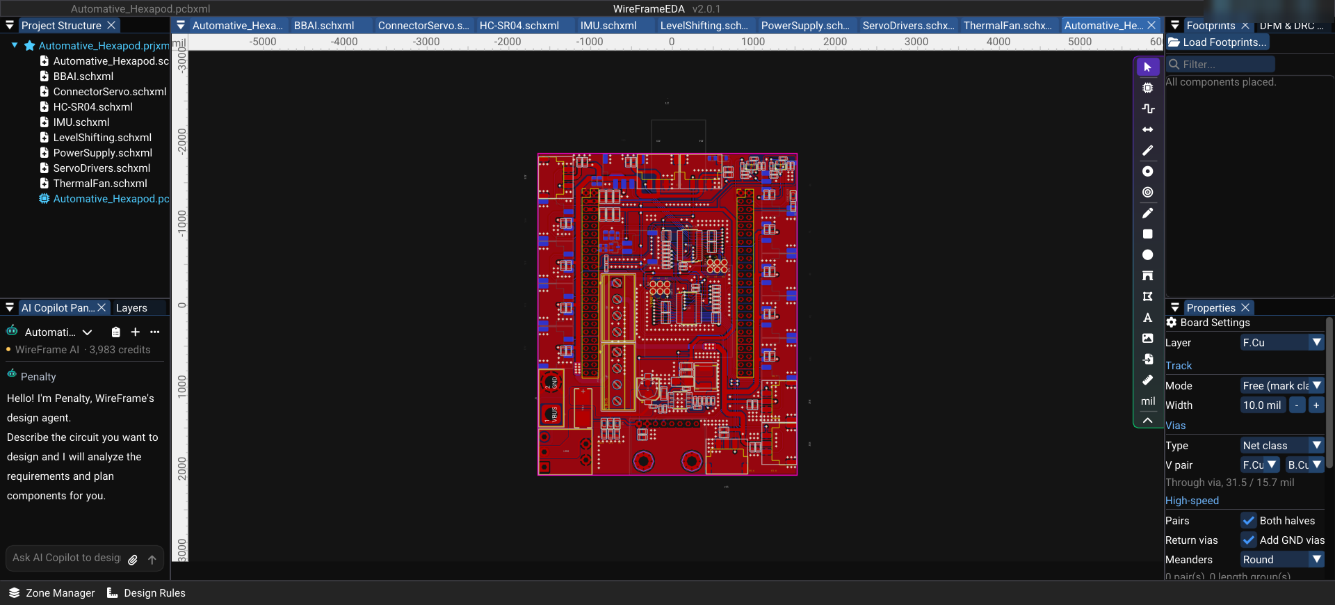
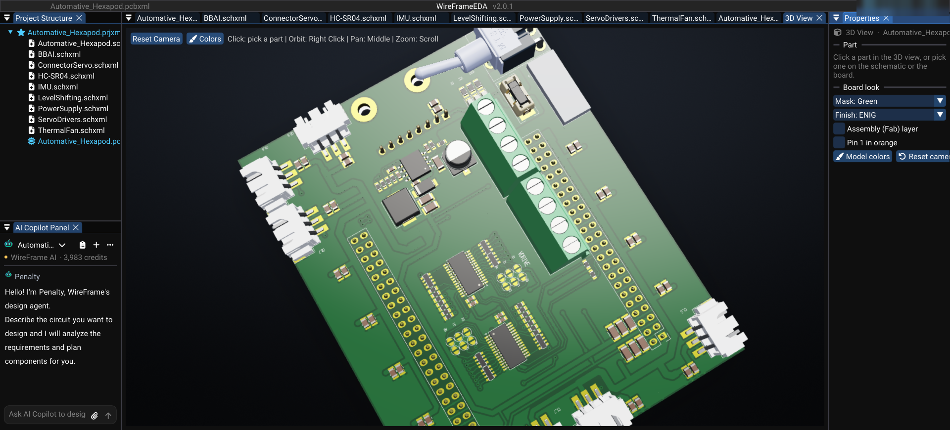
This post looks at the hardware: the main board (version 1.1.0), opened in WireFrame EDA.
What is on the board#
The schematic is split into 9 sheets, one block each:
| Sheet | Main contents |
|---|---|
| BBAI | BeagleBone AI headers, status LEDs |
| ServoDrivers | 2 × PCA9685 (16-channel I²C PWM), solder jumpers for address select |
| ConnectorServo | 18 servo connectors, each with its own decoupling, on two servo supply rails |
| PowerSupply | TPS54331 buck, SS54 Schottky diode, fuse, power switch, battery input |
| IMU | MPU6050 (accelerometer + gyroscope) |
| HC-SR04 | Ultrasonic distance sensor |
| LevelShifting | 3.3 V ↔ 5 V MOSFET level shifters |
| ThermalFan | Cooling fan control |
For members
Keep reading — it’s free
Sign in or create a WireFrame account to read the rest of this post and every guide on the blog.
- The rest of this post — about 2 min of reading
- The same account signs in the WireFrame desktop app
- Free design tools, no time limit
Sign in to WireFrame
One account for the desktop app and this site.