3D, mechanics & products
Enclosure Fit and Board Stacks
On this page
Two tabs of the Component Review window deal with the physical product rather than the circuit:
| Tab | Answers |
|---|---|
| Board Fit | What shape is the board, does the BOM fit on it, and does it fit the case? |
| System | When the product is several boards, how are they stacked and wired to each other, and is anything wrong between them? |
Open them from AI Copilot's review window. Both are saved with the project. A design with no enclosure is not a design with a problem: nothing on these tabs is a fault until you give the board a case or a second board.
Board Fit#
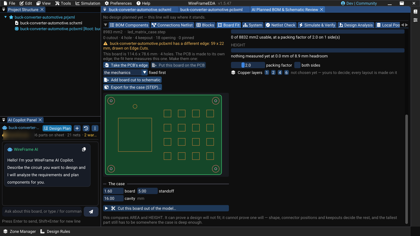
Board Fit works from the BOM and the mechanics alone — before the schematic is drawn and long before placement — so a board that cannot hold its parts is found early.
First: what is fixed already?#
The tab opens on one question, kept with the project, which decides where the board's size comes from:
| Answer | What follows |
|---|---|
| The mechanics | A case, a frame, a standard board or a drawing gives the shape; the parts have to fit it (below) |
| Nothing yet | The circuit decides: the board is sized from the BOM, and the case is made around it |
| Only limits | A largest size is fixed — a pocket, a slot, a product — and the board is sized from the BOM inside it |
Copper layers (1, 2, 4 or 6) are chosen here too, before any size: they change how much room the parts need. The count belongs to the project — every layout is made on it, and Update PCB builds the board on that many copper layers.
Sizes from the BOM. With nothing mechanical to follow, the tab offers sizes built from the parts, each one grown until the fit check agrees: Compact (the least square), Edge row (long enough for every part that must stand at one edge, when Compact's side is too short) and Roomy (more room, 4:3). Beside each: its area, aspect, the fit verdict, how much of one side the edge parts take, and whether it stays inside your limits. Use this size makes it the board — a plain rectangle you then shape on this tab or with /board.
Give the board a shape#
Pick one of these on the tab:
| Button | Use it for |
|---|---|
| 3D model(s)… | A case, frame, tube, or a board you will stack on, as STEP, IGES, STL, 3MF, or OBJ — one file or several. The outline, holes, and heights are already in it |
| Standard board… | Raspberry Pi HAT / micro-HAT, Arduino UNO shield, or FPV stacks 30.5 / 25.5 / 20 / 16 mm, each from its published drawing |
| Board outline (SVG / DXF)… | The shape only; heights are typed afterwards. See Board Shape and Outline |
Or describe it in chat: /board 100x80 mm, M3 holes 4 mm in from each corner, or /board two boards on the 30.5 stack, 6 mm apart.
The board preview is drawn from above, +Y down as on the PCB: green the board, white holes and cutouts, red keepouts, orange openings in the lid, purple parts the case pins in place.
3D files#
Add 3D files… copies each file into the project so it reopens with it. For each file you can set:
- which way is up in the file;
- the unit — STL and OBJ carry none and are read as millimetres; a board 25× too small or too large means the file was in inches or centimetres;
- what the file is — a case, a lid, a frame, a board. Mark the lid file: its openings decide where the display and the keys go, and those parts are pinned under them.
Cut this board out of the model… lists the model's upward-facing surfaces so you can use one as the board. When a model already contains boards — a flight stack, a Raspberry Pi — Use the boards in the model takes them as the stack, with their outlines, holes, thicknesses, and spacers.
For the screw holes, the hole a screw passes the board through is what counts. Leaving it at zero takes the bore under it, which in a plastic boss is usually the pilot hole the screw bites into (2.5 mm for M3) — too small for the board.
Stacks of boards#
Board above… adds another board on top: a HAT, the flight controller over the ESC, the next board in a tube. A HAT or shield is moved so its holes land on the holes of the board below. Each board has a spacer below it — a standoff's length or a stacking header's mated height, which only you can state. What caps the tower (the lid's underside, a top plate) is set from the base; leave it at 0 and the top board's headroom is not checked.
Each board in the stack can be bound to a PCB file. Update PCB then gives that file the board's outline, holes, and heights.
/topology in the chat compares one board against a tower, and which parts go on which board, side by side.
Does the BOM fit?#
What it has to hold measures the area each part really needs against the board, with the height of each part against the case. The area factor is a multiple of the courtyard for clearance, routing channels, and fanout — a judgement, not a measurement: a hand-assembled two-layer board needs more room than a dense four-layer module. both sides is off by default, because a design that only fits by using both faces is a decision to make on purpose.
With several boards, BOM across the boards proposes which block goes on which board: blocks are kept whole, parts the case pins and parts already assigned stay where they are, and each remaining block — largest first — goes where most of its signals already are, on a board with room. The proposal is shown with the reason for each block; nothing moves until you accept it.
Export the board for the case maker#
Export for the case (STEP)… writes what a mechanical CAD tool needs to draw a case around the board: the board itself (outline, cutouts and holes, at its thickness), named and coloured, and
- once the board is laid out, every part on it as its courtyard box at its stated height, on its side;
- before layout, one keep-in block as tall as the tallest part — only when every part states a height.
A part with no known height is never given a guessed one: it goes in as a thin red marker named HEIGHT UNKNOWN, and the export says how many there are. The thickness is the board's, the PCB's stated stack-up, or 1.6 mm said as the fab default.
Put the board on the schematic#
The board can be added to the schematic as a part: a BOARD CUT box on the root sheet, with a footprint that carries the outline and cutouts on Edge.Cuts, the holes as NPTH pads, and courtyards around them. Update PCB then carries it like any other part, and it follows any later change to the board shape.
System: products made of several boards#
A product of several boards — a flight stack, a HAT on a Pi, a display cabled to the main board — is one project with a PCB per board, each on a level of the board stack above, and one assembly (.asmxml) that says which boards make the product and how they are wired to each other. The System tab of this window shows that assembly: the boards, the connections pin by pin, the findings between boards, and the tower in 3D.
Everything about it — creating an assembly, bought boards such as a Raspberry Pi or a BeagleBone, the checks between boards, and splitting one design into several boards with the Copilot — is on its own page: Multi-Board Products.