PCB layout
Board Shape and Outline
On this page
A WireFrame board is an object with a real shape: an outer edge, cutouts, mounting holes, keepout areas, openings, and parts pinned to a fixed position. Zone fills, the board clipper, DRC, the 3D viewer, and Gerber output all follow that shape, and it is drawn on Edge.Cuts for you.
There are three ways to set it:
| Source | Use it when |
|---|---|
| File → Import → CAD Outline (.svg / .dxf)... | A mechanical drawing of the board already exists |
/board <description> in AI Copilot |
You can describe the board in a sentence |
| Board Fit tab → Standard board… or 3D model(s)… | The board follows a known form factor or must fit an enclosure — see Enclosure Fit and Multi-Board Products |
Set the shape once. Do not also draw a second outline by hand on Edge.Cuts; two answers to "where is the board" is exactly the error the board shape exists to prevent.
Import a board outline from SVG or DXF#
- Open the PCB.
- Select File → Import → CAD Outline (.svg / .dxf)... and choose the file.
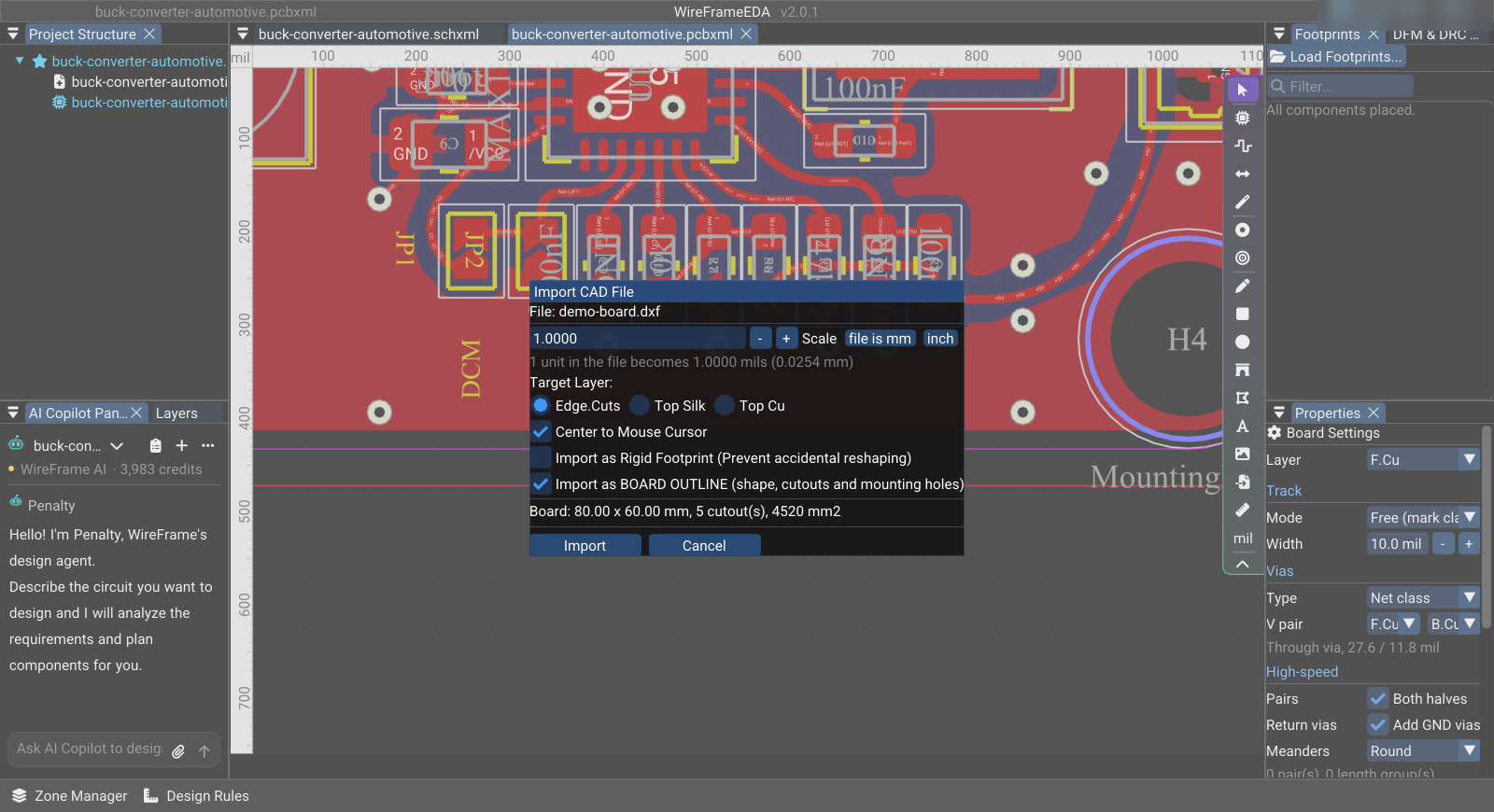
- In Import CAD File, tick Import as BOARD OUTLINE (shape, cutouts and mounting holes).
- Read the verdict that appears under the checkbox before importing:
- Board: W × H mm, N cutout(s), area mm² — check the size against the mechanical drawing.
- BLOCKS: — the file cannot become a board as it is; Import stays disabled.
- warn: and note: — importable, but read them; each is followed by -> and what to change.
- Select Import.
The verdict updates as you change the scale, so a wrong unit shows up as a wrong size before anything enters the board.
Units#
| Format | How the size is decided |
|---|---|
| DXF | From the drawing's $INSUNITS (millimetres or inches). A file that states no unit is read as millimetres, with a warning telling you to check the size |
| SVG | From the Scale field: mils per file unit. Use file is mm for a drawing in millimetres or inch for one in inches; the line under the field shows what one file unit becomes |
What the DXF reader understands#
ASCII DXF, section ENTITIES: LINE, LWPOLYLINE (including bulges, i.e. rounded corners), POLYLINE/VERTEX, CIRCLE, ARC, and SPLINE (fit points or control points). Blocks (INSERT) and binary DXF are not read. Anything skipped is named in the verdict — an outline placed as a block produces a warning, not a silent empty board. Explode the block in your CAD tool, or redraw it as lines, arcs, or a polyline.
Circles inside the outline become holes through the board.
Open strokes are joined end to end into closed outlines. A chain that does not close is reported with the gap, for example "ends finish 0.30 mm apart", so you know what to fix in the drawing.
Mechanical drawings are +Y up while the board is +Y down; WireFrame flips DXF geometry on import so a connector notch stays on the correct edge.
DXF needs the board-outline option
DXF files are read only when Import as BOARD OUTLINE is ticked. Importing graphics onto Edge.Cuts, Top Silk, or Top Cu without that option, and the Import CAD button on the PCB toolbar, read SVG only.
Importing SVG artwork instead of an outline#
With Import as BOARD OUTLINE unticked, an SVG is imported as graphics. Choose the Target Layer — Edge.Cuts, Top Silk, or Top Cu — and optionally:
- Center to Mouse Cursor — place the drawing where the cursor is instead of at its file coordinates;
- Import as Rigid Footprint (Prevent accidental reshaping) — keep the drawing as one footprint so it moves as a whole.
The Import CAD (SVG) button on the PCB toolbar opens the same dialog for SVG files.
Describe the board in AI Copilot#
With a project open, type the board in plain words:
/board 100x80 mm, 3 mm corners, four M3 holes 4 mm from each corner
Copilot turns the sentence into shape edits — outline, mounting holes, cutouts, keepouts, openings, pinned parts, heights — and every edit goes through the same checks as an imported outline. If one edit is refused (for example a hole that crosses the board edge), nothing changes and the reply names the edit and the reason. The result opens on the Board Fit tab.
Type /board with no description to print the current shape without a model call.
The shape is stored with the project, and every board of the project follows it.
Saved with the board#
The shape is saved inside the .pcbxml (older files that only have a rectangle still open). Because WireFrame projects the shape onto Edge.Cuts, copper zones automatically avoid cutouts such as a battery pocket, and Gerber output carries the same edge.
Before fabrication#
- Compare the reported size with the mechanical drawing.
- Check mounting holes against the enclosure or standoffs.
- Confirm keepouts under antennas, connectors, and mechanical parts.
- Run DFM & DRC Check — board-edge and hole checks use this shape.