Schematic
Wiring and Nets
On this page
Wires connect component pins into electrical nets. This page covers drawing wires, connecting pins, placing net labels, and using power symbols.
Drawing Wires#
Activating the Wire tool#
Press W or click the Wire button on the toolbar.
How to draw a wire#
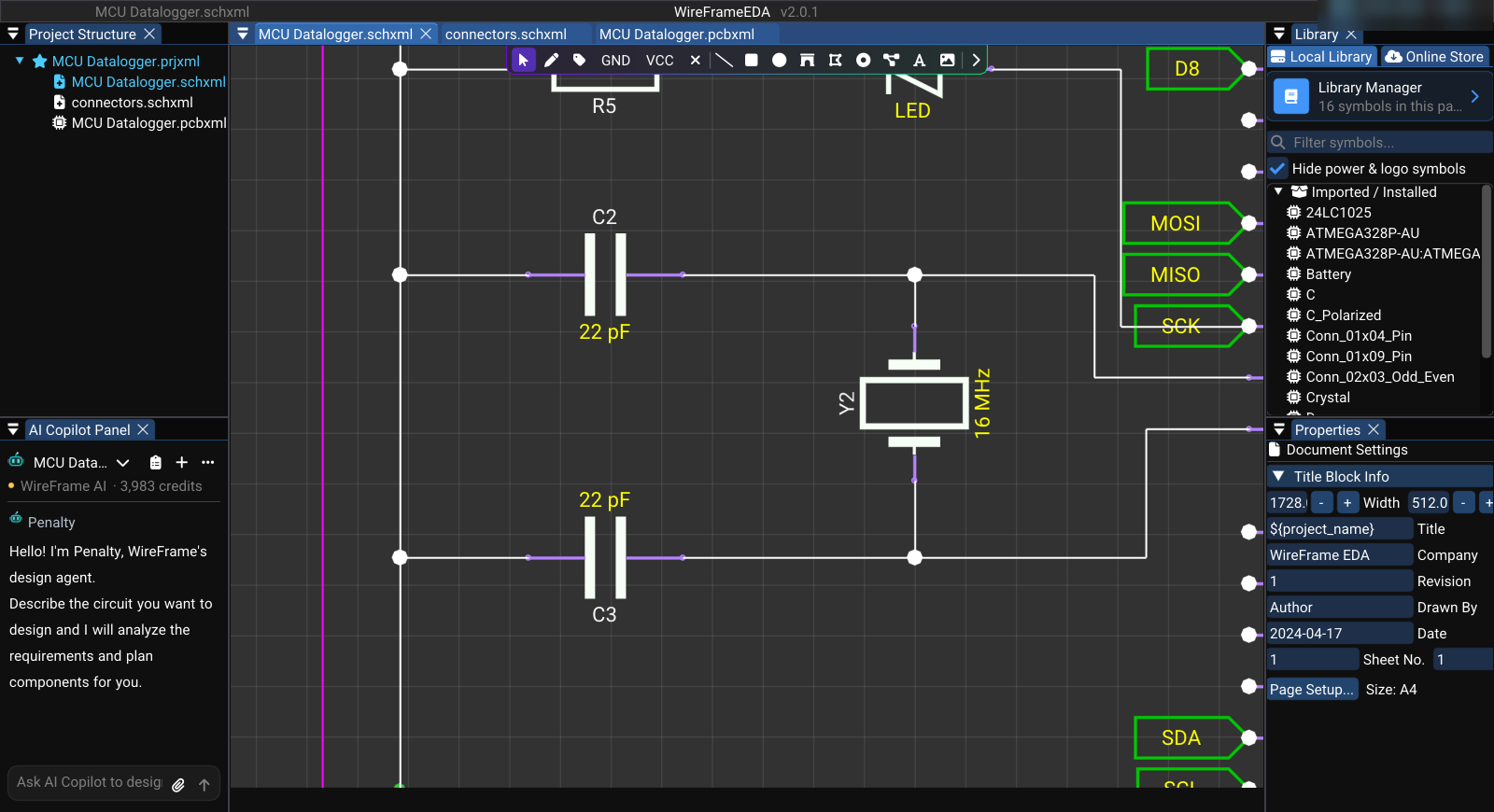
- Click on a component pin (or any point on the canvas) to start a wire
- A temporary wire follows the cursor — drawn orthogonally (horizontal and vertical segments only) and snapped to the grid. Press Space to flip whether the first bend goes horizontal or vertical
- Click to add each corner vertex
- Click a pin or an existing wire to finish there — the wire snaps to it. To finish at a free point, double-click
- Esc cancels the wire you are drawing
| Action | Input |
|---|---|
| Start a wire | Click on a pin or canvas point |
| Add a corner | Click |
| Flip the bend direction | Space |
| End on a pin or wire | Click it |
| End at a free point | Double-click |
| Cancel the wire being drawn | Esc |
| Leave the Wire tool | Esc again |
Starting from a pin snaps automatically
When you click on a pin tip, WireFrame snaps the first vertex precisely to that pin — no manual alignment needed.
Connecting Wires to Pins and Existing Wires#
To another pin#
- The final vertex snaps to the target pin position
- Both pins are now on the same net
To an existing wire#
- The new wire shares the meeting point with the existing wire
- WireFrame merges them into a single net
Use the shared GND net label or power symbol at the intended connection points. WireFrame merges connected wire segments and matching global power labels into the same net.
Junction Dots#
A junction dot appears when three or more wires meet at a single point:
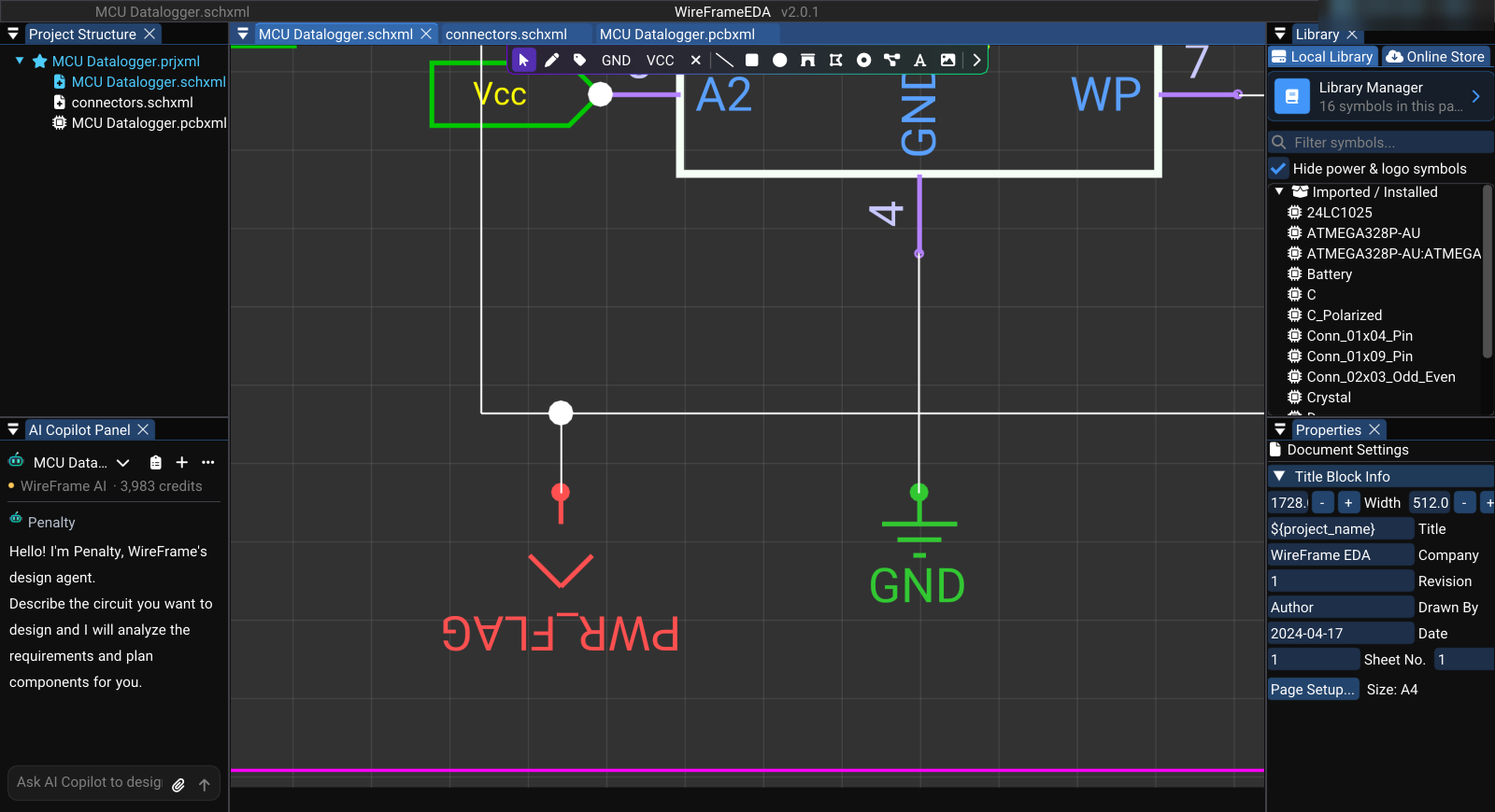
- Junction dots are placed automatically when three or more connections share a point
- You can also place them manually with the Junction tool
- Two crossing wires without a junction are not electrically connected
Editing Existing Wires#
| Operation | How |
|---|---|
| Move a vertex | Drag a point on the wire |
| Drag a segment | Click and drag a segment between two vertices → adds two new vertices, moves orthogonally |
| Delete a wire | Select + Del |
Auto-simplification
After dragging a segment, WireFrame automatically removes redundant collinear vertices — keeping the wire geometry clean.
Net Labels#
Net labels allow you to connect two points electrically without drawing a wire between them. Labels with the same name belong to the same net.
How to place a net label#
- Press N or click the Label tool
- Click on the canvas to place a label. It gets a suggested name such as
NET_1 - Select it and edit the Value in the Properties panel (e.g.
SDA,SCL,+3V3,RESET) - All wires connected to that label share the same net name
For example, matching SDA labels at the controller and sensor place both endpoints on the same named net even when no wire spans the page between them.
Use consistent names
All labels with the same name (e.g. +3V3) merge into a single net — even on different parts of the sheet. This is the cleanest way to distribute power to multiple components.
Power Symbols (GND, VCC)#
| Symbol | Shortcut | Description |
|---|---|---|
| Place GND | G | Ground reference — implicitly connects all GND pins |
| Place VCC | P | Positive supply rail, named VCC; change its Value (e.g. +3V3) for another rail |
Power symbols are single-pin components that automatically assign a net name to any wire connected to them.
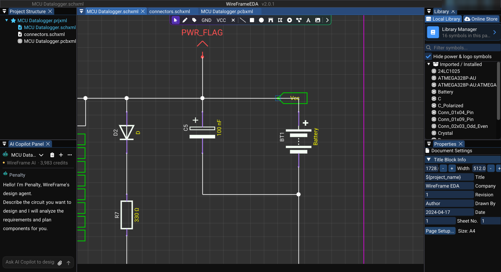
The KLP4e datalogger brings its supply to each part with net labels named Vcc rather than with a supply symbol, and ground with GND symbols — both are ways of naming a net. The PWR_FLAG markers come from the KiCad project; WireFrame keeps them on the sheet as drawn.
Net Highlighting#
Click on any wire or net label: - All wires and pins on that net are highlighted in a distinct color - Useful for tracing connectivity in complex schematics
Click on empty canvas to clear the highlight.
Auto Wire#
Tools → Auto Wire draws wires for the connections the active schematic's netlist already contains, using an orthogonal router that runs locally (no AI request is sent). Use it to tidy a sheet whose connectivity is right but whose wiring is missing or messy, then inspect:
- that every wire ends on the intended pin;
- that labels and junctions are still readable;
- that no wire crosses a symbol or hides an annotation.
A whole auto-wire run is one step in the undo history — Ctrl+Z takes it back.
How the Netlist is Built#
WireFrame automatically constructs the netlist from all wires, pins, and labels:
- Groups all wires that share vertices into clusters
- Collects all pins attached to each cluster
- Determines the net name by priority:
- Net label / power symbol values (highest priority)
- Pin-based default names (e.g.
Net_U1_1) - Wire-based fallback names (e.g.
Net_Wire_42)
This netlist is used for: - Net highlighting on the canvas - PCB netlist generation when converting to PCB - DRC consistency checks between schematic and PCB
See Also#
- Placing Components — place the symbols that wires connect
- Properties & Attributes — edit net names and component values
- PCB Editor — the netlist built here drives PCB routing