PCB layout
Zones and Copper Planes
On this page
Copper zones (fills / pours) cover a board area with copper — typically used for ground planes or power planes. This is a standard practice in professional PCB design.
Why Use Zones?#
- Ground plane — reduces EMI noise and improves RF signal integrity
- Power plane — reduces voltage drop on power rails
- Larger copper area → lower impedance → better heat dissipation
What Is a Zone?#
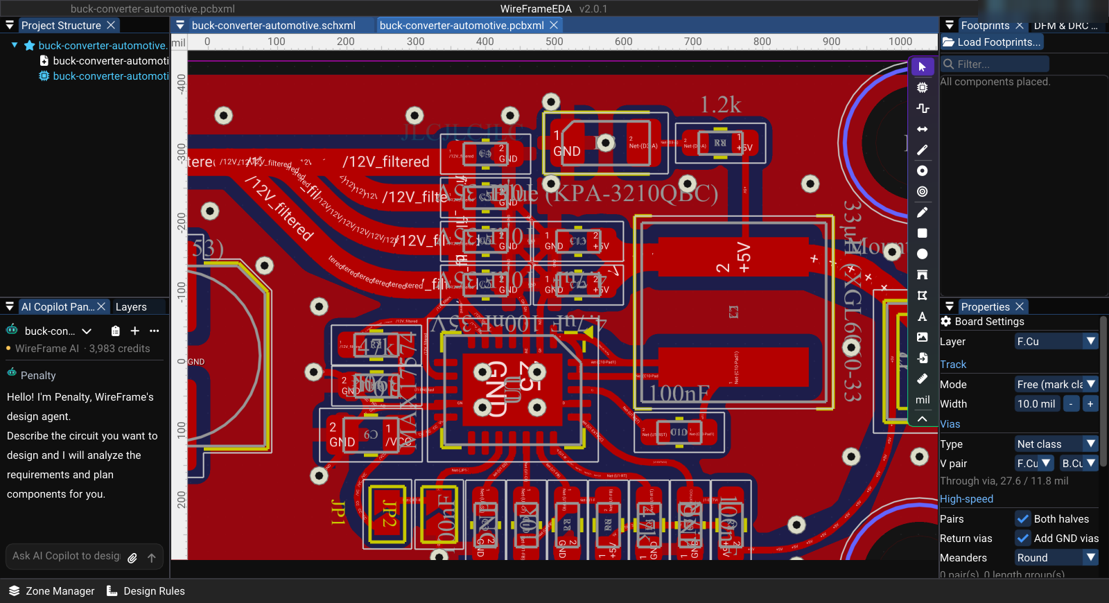
A filled zone follows its outline while maintaining clearance around objects on other nets. Pads on the zone net connect according to the configured zone connection style.
Each zone has:
| Property | Description |
|---|---|
| Net | The net name (e.g. GND, VCC) |
| Layer | Copper layer (e.g. F.Cu, B.Cu) |
| Priority | Higher-priority zones override lower ones where they overlap |
| Clearance | Minimum gap from pads and traces on other nets |
| Outline | The polygon you draw to define the zone boundary |
Quick Ground Plane#
The fastest way is the Zone Manager (View → Zone Manager):
- Select GND plane ▾ and choose Top and bottom, F.Cu, or B.Cu. WireFrame adds a
GNDzone on that layer (see where the outline comes from). - Select Refill to compute the copper. A new pour holds no copper until it is filled, so you can set priorities first.
The fill keeps clearance around pads and traces on other nets and connects GND pads into the copper. Adding the plane is one undo step.
Ground plane on an inner layer
The GND plane menu lists every copper layer of the stackup, but it only creates zones on F.Cu and B.Cu. For an inner layer such as In2.Cu, use + Pour, pick that layer, and choose the net GND.
Zone Manager#
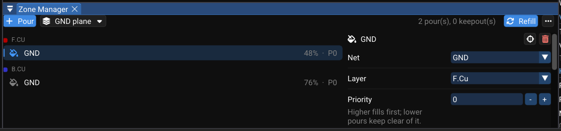
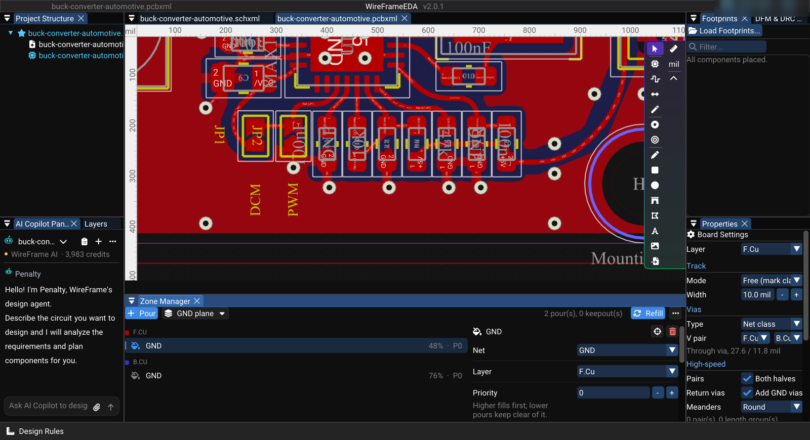
View → Zone Manager opens a panel, docked below the canvas by default, that lists every copper zone and keepout of the active board.
Top bar#
| Control | What it does |
|---|---|
| + Pour | Opens Whole-board pour: pick a Layer (any copper layer, inner layers included) and a Net (the list has a search box), then Add pour |
| GND plane ▾ | Adds a GND pour on Top and bottom, F.Cu, or B.Cu |
| n pour(s), n keepout(s) | How many zones the board has. On a narrow panel this count moves into the Refill tooltip |
| Refill | Recomputes every fill from the copper around it, in the background. The button reads Filling... until it finishes |
| ⋯ → Unfill all | Clears the computed copper but keeps every zone and its settings. Refill fills them again |
| ⋯ → Remove all zones... | Deletes every zone and keepout after a confirmation. One undo step brings them back |
New pours never replace existing ones. Pressing GND plane twice creates two overlapping GND zones — delete the extra one.
Where a new pour gets its outline#
+ Pour and GND plane take the zone outline from the first of these that exists:
- Polygons or rectangles you have drawn on that copper layer — each one becomes a zone. Draw the area first when a plane should cover only part of the board.
- The board outline on Edge.Cuts.
- Without an outline: a rectangle around the placed footprints, with a 200 mil margin.
Zone list and details#
The left side lists the zones grouped by copper layer, in stackup order and highest priority first. Each row shows the net (or Keepout), how much of the outline is filled, and the priority (P0, P1, …). Zones with the same layer, net, priority, and name are one row, marked ×n. A row at 0% has not been filled yet — select Refill — or has no copper of its net to join. Double-click a row to zoom to it.
Select a row to edit it on the right:
| Field | Meaning |
|---|---|
| Net | The zone's net; <No net> for an unconnected copper area |
| Layer | Copper layer |
| Priority | Higher fills first; lower pours keep clear of it — see Zone Priority |
| Clearance | Gap to copper of other nets, shown in mil or mm |
| Min width | Slivers of copper narrower than this are removed |
| Thermal relief | Spokes to pads of its net so they can be soldered; Spoke width sets their width |
| Keepout rules | For a keepout: No tracks, No vias, No pads, No copper pour, No footprints |
The buttons beside the title centre the view on the zone or delete it (one undo step brings it back). The line at the bottom shows the outline area, the filled percentage, and the number of copper islands.
Every change is one undo step (Ctrl+Z), and the board refills automatically after an edit in this panel.
Creating a Zone of Your Own Shape#
- Select a copper layer (e.g. F.Cu) in the Layer panel.
- Draw a closed shape on it with the Draw Polygon or Draw Rectangle (R) tool.
- In the Zone Manager, select + Pour, choose the same layer and the net (e.g.
GND), then Add pour. Every polygon or rectangle on that layer becomes a zone of that net. - Set Priority, Clearance, and Thermal relief for the new row, then Refill if it is still at 0%.
Keepout areas are not drawn by hand: they come with an imported KiCad board or from a /layout proposal, and appear in the Zone Manager as Keepout rows.
Zone Priority#
When two zones overlap, the zone with the higher priority wins:
The higher-priority zone owns the overlapping copper area; the lower-priority zone remains in the rest of its valid outline.
Priority guidelines
- Ground plane → priority 0 (lowest)
- VCC island inside the GND plane → priority 1
- Zone nested inside VCC → priority 2, and so on
How Zones Interact with Nets#
| Situation | Result |
|---|---|
| Pad on the same net as the zone | Pad connects directly to the fill (no ratsnest) |
| Trace on the same net passing through | Trace connects to the zone |
| Pad on a different net inside the zone | Clearance gap is maintained around the pad |
| Trace on a different net inside the zone | Clearance gap is maintained around the trace |
Editing Zones#
| Change | Where |
|---|---|
| Net, layer, priority, clearance, min width, thermal relief | Zone Manager, on the selected row |
| Position | Click the zone on the canvas, then drag it or nudge it with the arrow keys (5 mil per press) |
| Shape | Delete the zone, change the drawn polygon or rectangle on the copper layer, and pour again |
| Remove | Delete with the zone selected, or the delete button in the Zone Manager |
See Also#
- Routing — traces interact with zone clearances
- DFM & DRC — zone connectivity is validated during DRC
- Layers & Views — zone visibility follows layer settings