3D, mechanics & products New
Multi-Board Products
On this page
A product is often more than one board: a HAT on a Raspberry Pi, a cape on a BeagleBone, a flight controller on an ESC, a front panel cabled to a main board. In WireFrame such a product is one project:
hexapod.prjxml
├── main.pcbxml   ← main.schxml  (+ main_… sheets)     level L1 of the board stack
├── panel.pcbxml  ← panel.schxml (+ panel_… sheets)    level L2
└── hexapod.asmxml ← the boards, the bought boards, and how they are wired to each other
- each board is a
.pcbxml, drawn from its own root sheet; - each board sits on a level of the project's board stack — the tower Board Fit draws, with the spacer under each board;
- one assembly (
.asmxml) names the product's boards — the project's PCBs, a PCB of another project (an open-source shield), and boards you buy rather than design — and every connection between them.
The problems no single board can show are checked here: a 5 V pin meeting a 3.3 V pin, SDA wired to SCL, a cable turned round, signals crossing without a ground beside them.
Create and open an assembly#
| Menu | What it does |
|---|---|
| File ▸ New ▸ New Assembly (.asmxml)… | Makes the active project's assembly: its PCBs as its boards, each named after its board-stack level |
| File ▸ Open Assembly (.asmxml)… | Opens an assembly and its project (File ▸ Open File… takes an .asmxml too) |
| File ▸ Close Assembly | Closes it |
| View ▸ Assembly View | The assembly in its own centre window, like the 3D view |
The assembly sits under its project in Project Structure, follows the project you work in (activating the project opens its assembly) and reopens with the session. The System tab of the AI review window shows the same content while the Assembly view is not on screen.
The Assembly view#
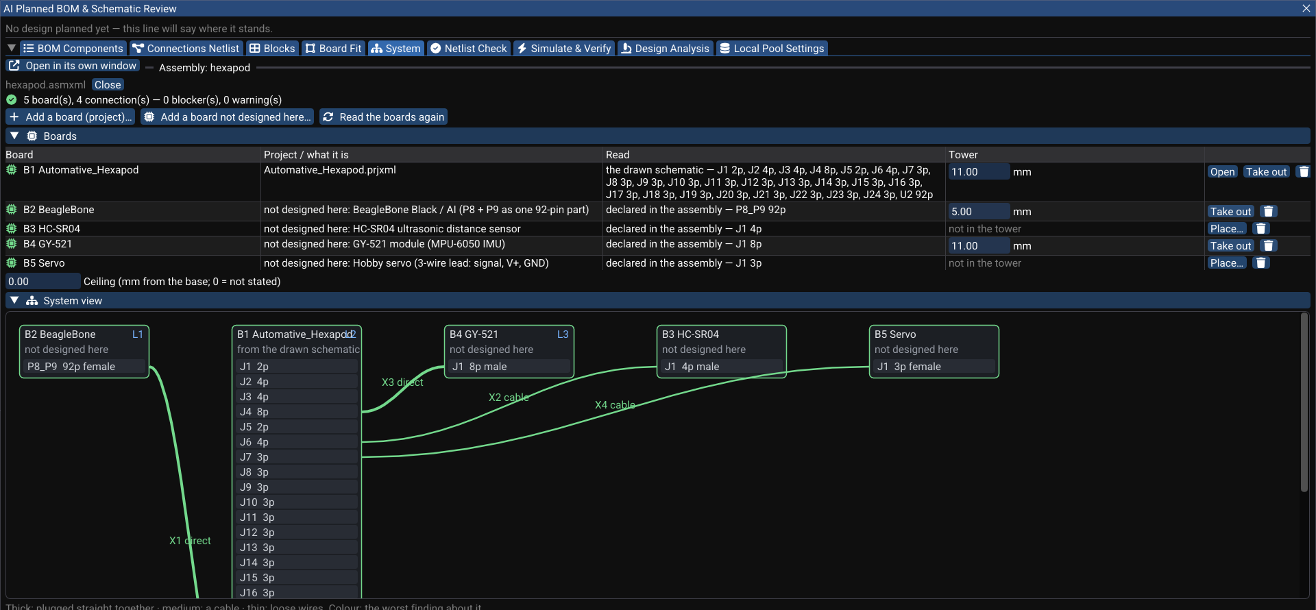
Boards lists each board: what it is, how it was read (the drawn schematic, its share of the design plan before its sheets exist, or declared in the assembly for a bought board), and where it sits in the tower. Open opens a board's project; Take out removes it from the tower; Place… puts it in.
- Add a board (project)… — a PCB of this project or of another one.
- Add a board not designed here… — a bought board, from its published pinout (below).
- Read the boards again — after you edit a board.
System view draws the boards as blocks and their connectors as entries. Line thickness is the kind of link — thick: plugged straight together, medium: a cable, thin: loose wires — and colour is the worst finding on it. Each connection opens pin by pin.
Assembly 3D shows the tower in its case, built in the background: Boards, 3D files and See through the case toggles, Explode to lift the boards apart for looking (the checks always use the real spacers), and Fit. A spacer changed here is changed in Board Fit, and the other way round.
Connections#
Each connection joins a connector on one board to a connector on another:
| Kind | Example |
|---|---|
| direct | A stacking header pair; a HAT socket on the Pi's 40-pin header |
| cable | A JST or FFC lead, with its length |
| wire | Loose wires soldered to pads |
The pin map is pin for pin unless you state it (an FFC with contacts on opposite sides reverses it: 1 meets N). A shield whose header block is drawn as one part over several headers (an Arduino shield's 28 pins over four headers) is connected in parts: one connection per header, each listing its pins, and no pin used twice. A host's pin named for where it is (A0, D7, GPIO17, PA5) meeting the name of what the plugged-in board uses it for (XSTEP) is what a header is for, not a naming conflict.
Bought boards#
Boards nobody designs here come from their published pinouts: which pins are fixed (rails and grounds), which take a signal, which take a supply in a range, which are spare — so they are checked pin by pin like your own.
| Template | What it is |
|---|---|
rpi-40 |
Raspberry Pi 40-pin GPIO header (Pi 2, 3, 4, 5, 400 and Zero) |
beaglebone / beaglebone-92 |
BeagleBone Black / AI P8 + P9 headers (as two connectors, or as one 92-pin part) |
hc-sr04 |
HC-SR04 ultrasonic sensor (its ECHO is a 5 V output) |
servo |
Hobby servo lead (signal, V+ 4.8–7.4 V, GND) |
gy-521 |
GY-521 module (MPU-6050 IMU) |
pololu-a4988 |
Pololu A4988 stepper driver carrier (and pin-compatible StepStick / DRV8825 carriers) |
Standard board shapes — Raspberry Pi HAT and µHAT, Arduino UNO shield, FPV 30.5 / 25.5 / 20 / 16 stacks — are in Board Fit (Standard board…), see Enclosure fit.
What is checked between boards#
| Finding | Example |
|---|---|
| Two different rails joined | A 5 V pin on a 3.3 V pin |
| A supply or ground meeting a signal | GND on a GPIO; 5 V on a sensor's GND |
| Pins trading places | SDA on SCL, TRIG named on ECHO — reported as one finding |
| A pin order reversed end to end | An FFC turned round — one blocker |
| One wire under two names | Reported as a note when it is the same rail (VDD_3V3 meets +3.3V) |
| A pin open on one side | A signal that goes nowhere on the other board |
| Signals with no ground beside them | A cable carrying fast signals without a return |
| Two connections shorting one board's nets | The same net reached twice through different connectors |
| A direct pair that cannot mate | Same gender, not over each other, mated height ≠ spacer |
| Supply voltage not stated | A rail whose name states no voltage meets a pin with a range — said so, not guessed |
The summary reads N board(s), N connection(s) — N blocker(s), N warning(s). The hexapod in the picture reads with no blocker and no warning — four notes that the BeagleBone's VDD_3V3/VDD_5V are the cape's +3.3V/+5V, and one that the servo rail's name states no voltage. Turn the HC-SR04 lead round and cross the GY-521's SDA/SCL, and it reports two blockers (5 V on its GND, ground on its VCC) and both crossings.
From one design to several boards#
When a design should become several boards, ask the Copilot — /topology, or in plain words ("one board or a tower?"). It:
- reads the design's blocks and the nets a cut between two blocks would carry;
- proposes two to four genuinely different splits and measures each the same way — each board's parts against its room, what crosses between each pair of boards and how many connector pins that costs, the tower against its ceiling — and argues from those numbers;
- applies a split only with your words: connectors from real families (stacking headers, JST-SH/GH/PH/XH, IDC, FFC, wire pads), a pinout you can state, written into the project — each board's connectors in the plan, the board stack, a
.pcbxmlper board, and the project's.asmxml; - Build Sheets then draws a root sheet per board with only that board's parts, and Update Schematic to PCB from each root makes its board.
Limits today#
- Pins have no logic level yet: a 3.3 V host driving a 5 V-supplied part's input is not caught.
- System-on-module connectors (CM4/CM5, Jetson SO-DIMM) are declared by pin count only.
- Only the A4988 and BeagleBone templates say where their pins are; other bought boards are not checked for alignment.
- No interference check between the boards and the case: the Assembly 3D shows it, nothing reports it yet.
See also#
- Enclosure Fit — the board stack and shapes from a case
- 3D Viewer
- File formats —
.asmxml