Simulation
Testbenches and Measurements
On this page
A waveform tells you what happened. A testbench lets you record what the circuit should do and asks WireFrame to check it after every run. A testbench belongs to the simulation it is written in; the sheets of the design never see its loads or checks.
A simple verification workflow#
Add the expected load, choose a signal, define an acceptable limit, and run the simulation. Treat Pass as evidence for that requirement, Fail as a circuit or setup issue to investigate, and Not measured as an incomplete check.
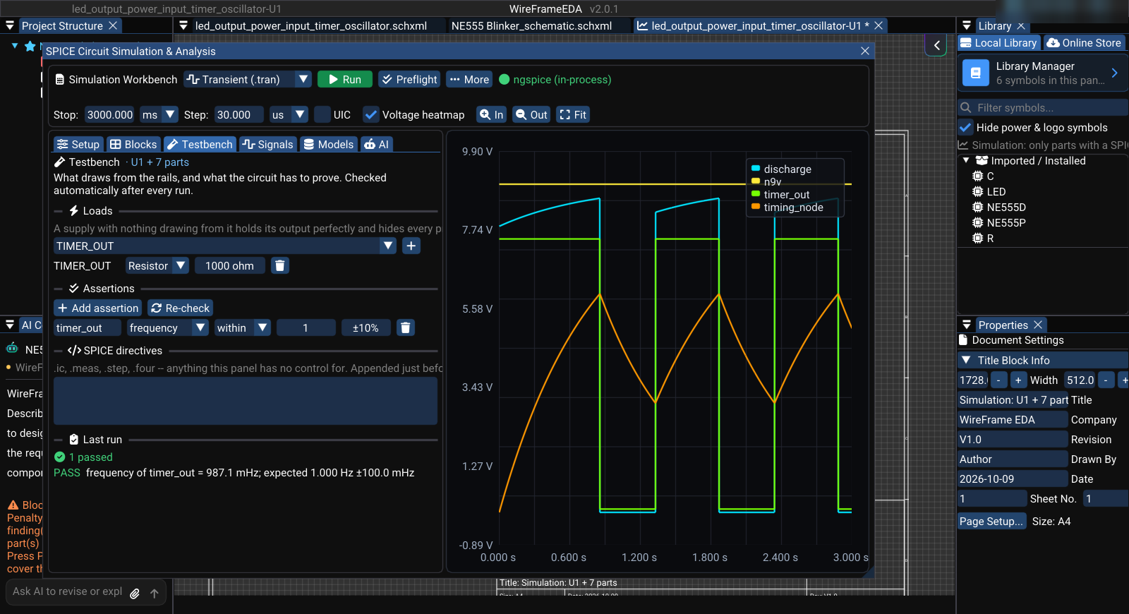
Open the Simulation Workbench and select the Testbench tab. The heading names the circuit it applies to.
Add a load#
Real circuits must power something. An output with no load can look better than it will in the final product.
- Under Loads, choose the output net.
- Click Add.
- Enter the load required by your design.
- Run the simulation again.
Use values taken from the product requirement, connected device, or component datasheet.
Add an acceptance check#
- Under Assertions, click Add.
- Choose the signal to check.
- Choose a measurement.
- Select Within, At most, or At least.
- Enter the required value and tolerance.
- Run the simulation.
Common measurements#
| Measurement | Example use |
|---|---|
| Minimum / Maximum | Make sure a rail never leaves its safe range |
| Peak-to-peak | Check total ripple or signal swing |
| Mean | Check the average DC output |
| RMS / AC RMS | Check signal level or ripple without the DC component |
| Frequency / Period | Verify an oscillator or clock |
| Duty cycle | Verify a PWM output |
| Rise / Fall time | Check switching speed |
| Overshoot | Check startup or edge quality |
Exclude startup from a steady-state check#
Assertions measure the whole record of the last run. When a requirement applies only after startup:
- measure it between the A/B cursors: under Signals → Measurements, tick Measure between cursors, enable the cursors in Setup → View, and place them after the circuit has settled; or
- add a
.measdirective with aFROM/TOwindow under Testbench → SPICE directives.
For example, check the average VOUT after the regulator has settled instead of including its initial rise from 0 V.
Understand the result#
| Result | Meaning | What to do next |
|---|---|---|
| Pass | The measured value meets your limit | Keep the check and continue |
| Fail | The measured value is outside your limit | Inspect the waveform, source, load, and circuit |
| Not measured | WireFrame could not calculate the requested value | Check the selected signal, analysis, and measurement window |
Important
Not measured is not a pass. Also, WireFrame does not assume what a “good” value should be—you must enter the requirement you want to verify.
Ask Copilot for help#
When Copilot is connected, select Ask why beside a failed or unmeasured result. Copilot receives the current signal, testbench, and result so it can help you investigate.
Review the explanation against the waveform and datasheet before changing the circuit.
Before moving to PCB#
- Use the same supply voltage and load expected in the final product.
- Add checks for every important output.
- Separate startup requirements from steady-state requirements.
- Resolve every Fail and Not measured result.
- Save a CSV when you need to share verification evidence.